Motor
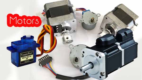
An electric motor is an electromechanical device that converts “electrical energy into mechanical energy”. Most electric motors operate through the interaction of magnetic fields and current-carrying conductors to generate force. These are the following type of motors.
- DC Motors
- Stepper motors
- servo motor
- universal motor
Now we are explaining above each motor one by one.
DC Motors
A DC motor is an electric motor that runs on direct current (DC) electricity. DC motor has simply two wires after giving them DC supply. It will rotate in one direction and its direction can be changed by changing the polarity. DC motor can operate directly from rechargeable batteries, providing the motive power for the first electric vehicles.
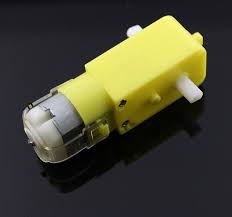
Principles of operations:
- In an electric motor, operations are based on simple electromagnetism.
- The internal configuration of a DC motor is designed to harness the magnetic interaction between a current-carrying conductor and an external magnetic field to generate rotational motion.
We don’t connect DC motor with a microcontroller directly because to run motor needs some more current than the output of the microcontroller. To motor drive, we need current for the motor speed we need voltage. So to connect motor with the microcontroller we need an interfacing IC which is also called driver IC. There are different types of driver IC like L293D, L298D, ULN2803 and son many. Here we will bring L293D as a driver IC to interface motor with a microcontroller.
L293D
The L293D is ideal for controlling the forward/ reverse/ brake motors of Small DC motors controlled by a microcontroller such as an AVR, 8051 microcontrollers. The L293D is a quadruple push-pull 4 channel driver capable of delivering 600mA per channel. One L293D is capable of driving two DC motors at a time.
Features
- 16 pin DIP; 4 channel I/O
- 600mA output current capability per driver
- Wide supply voltage range 4.5 volts to 36 volts
- separate input-logic supply
- Tristate logic buffer IC
- works in Push-pull (sinking-sourcing mode)
- Internal clamp diodes, over temperature protection.
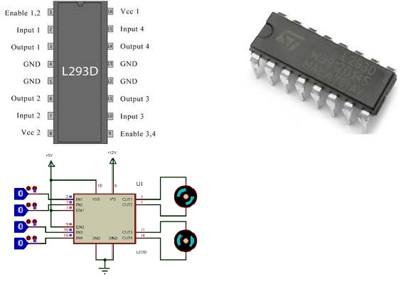
PIN Diagram
It is a 16 pin IC in which 4 input pins and 4 output pins. This single IC has a property to drive two DC motor at a time.
Configuration of ATMega 16 with L293d
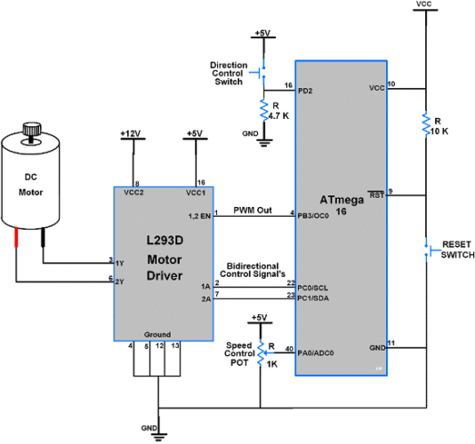
The L293D is a quadruple push-pull 4 channel driver capable of delivering 600mA per channel. One L293D is capable of driving two DC motor at a time.
Stepper Motor
A stepper motor is a brushless DC electric motor that divides a full rotation into a number of equal steps. The motor’s position can then be commanded to move and hold at one of these steps without any position sensor for feedback as long as the motor is carefully sized to the application in respect to torque and speed.
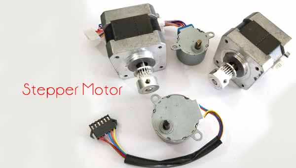
Switched reluctance motors are very large stepping motors with a reduced pole count, and generally, are closed loop communicate. Brushed DC motors rotate continuously when DC voltage is applied to their terminals. The stepper motor is known by its property to convert a train of input pulses (typically square wave pulses) into a precisely defined increment in the shaft position. Each pulse moves the shaft through a fixed angle.
Stepper motors effectively have multiple “toothed” electromagnets arranged around a central gear-shaped piece of iron. The electromagnets are energized by an external driver circuit or a microcontroller.
Also Check:UC Browser Review : Is UC Browser Safe? Risks, Solution
Types of Stepper Motor:
- Permanent Magnet Type
- A variable resistance stepper motor or without permanent magnet type
- Hybrid Type
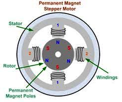
- Permanent Magnet Type:It has two coils A and B, which are wound around the upper and lower halves of the stator. The stator surrounds the rotor that contains a permanent magnet. When voltage is applied to the windings, the permanent magnet rotor of the stepper motor assumes its unloaded holding position. The permanent magnet poles of the rotor are aligned according to the poles of stator. The maximum torque with which the excited motor can be loaded without causing a continuous rotation is known as the stepper motor.
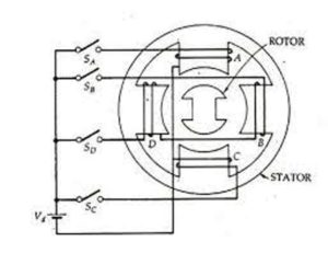
- Variable Reactance Stepper Motor:The Stator has a number of wound poles but the rotor has no windings. The number of poles on the stator is an even multiple of the number of phases for which the stator winding is wound. The number of phases on the stator must be at least 3 bidirectional control of the stepper motor.
The Stepper Motors have 12 poles on the stator and 8 poles on the rotor. Then it is called as3 phase variable reductance stepper motor. Also, it has no permanent magnet, therefore, it is called without magnet type motor.
Application of Variable Reactance Stepper Motor
- It is inexpensive
- It is suitable for light duties
- It is used in computer
- It is used in the industrial instrumental system.
Hybrid Stepper Motor
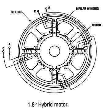
This motor is also called asPermanent Magnet Hybrid Stepper Motor. In this type of motor, the stator has 4 poles and each pole carries a winding and two coils are separately wound in the stator. In this motor, the step angle varies from 0.5° to 15° . The permanent magnet type hybrid has an excellent speed of 1000step/sec and cost is relatively high and it has higher torque capacity. The rotor has a bar magnet of N and S poles.
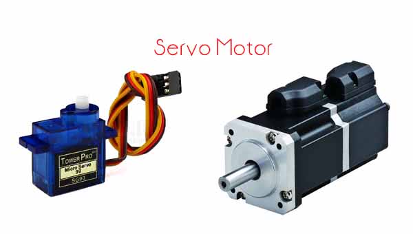
A servomotor is arotary actuator or linear actuator that allows controlling of angular/ linear position, velocity, and acceleration. It consists of a suitable motor coupled to a sensor for position feedback. It also requires a controller, often a dedicated module designed specifically for use with servomotors.
Servomotors are not a specific class of motor although the term servomotor is often used to refer to a motor suitable for use in a closed-loop control system.
Servomotors are used in applications such asrobotics, CNC machinery or automated manufacturing.
Servomotor Vs Stepper Motor
Basically, the Servomotors used as a high-performance alternative to the stepper motor. Stepper motors have the ability to control position, as they have built-in output steps, this method allows them to be used as open-loop system/ position control (without any feedback encoder), as their drive signal specifies the number of steps of movement to rotate, but for this the controller the position of the stepper motor can be known on power up.
Therefore, on first power-up, the controller will have to activate the stepper motor and turn it to a known position. It can be observed when we switch on an inkjet printer; the controller will move the ink jet carrier to the extreme left and right to establish the end positions. A servomotor will immediately turn to whatever angle the controller instructs it to, regardless of the initial position at power up.
Also Check:Best Tech Inventions |KeySearch Review
That’s all regarding chapter Motors. Next, we will deal with the switches and its types. So stay connect with us for more interesting topics in the Embedded System and Robotics.



Motors always fascinates me, magnetic fields n all and its application in the vibration of our phones to its industrial uses. This article really helps for the basics
Quick n understandable
Thank You Richa and have a nice day.
Hello sir
I am regular visitor of your post. I am so excited in this part. Will you also provide some interesting topics like Bluetooth, Gsm ect.
Hello Lakshya! Thanks to being a part of our Journey…. Yes We will cover all, but we are going slow to provide correct information, and covering topics from easy to hard. So Covered some basic components till now but we will cover almost everything soon. Thank You, Have a nice day and Keep Visiting.
Hey
Can u tell me wht is L & D in L293D ic of motor.
Hello Arnav!! L means “Low voltage” and D means “High Voltage”. Thank You for connecting with us. Next Chapter will be published Today, so Keep Visiting.
Nice post , wonderful website, keep up the good work.
Hii the article is too good, but can you give me some references of stepper motor ? so that I can go in deep details of it.