
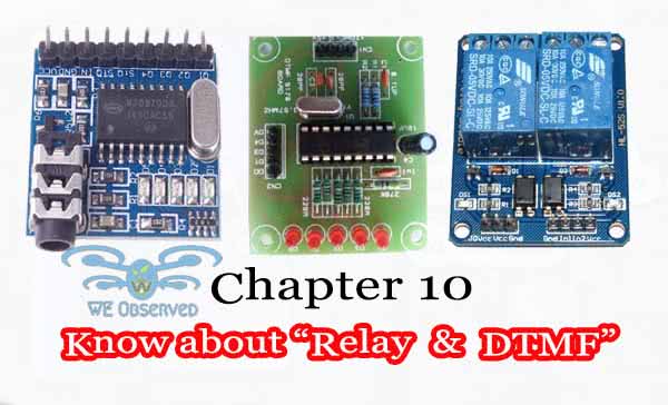
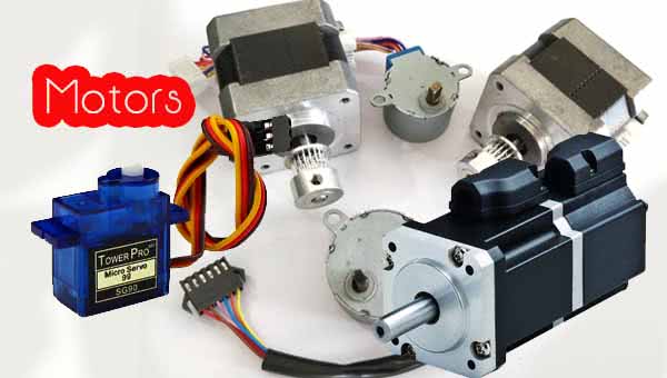
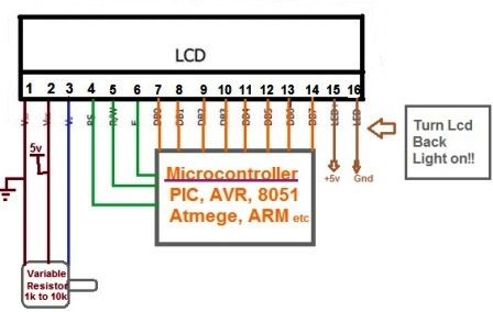
Relay and DTMF: Hello, Friends welcome back again. So far in Robotics, we learn about various topics like working of LCD, motors and its types, Switches and it’s types. We also learn about the difference between Microprocessor and micro-controller and most importantly the software in which we will work i.e. AVR (Advanced Virtual RISC).
Now connecting all those so far in this chapter we will learn about the Relay and DTMF (Dual Tone Multiple Frequency). We will learn its interfacing, working and how we can make some projects through that. So if you are interested in making projects based on Relay and DTMF go through this post.
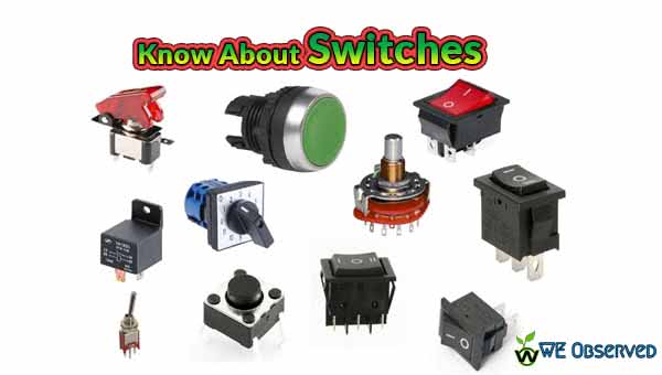
Previous Articles:Chapter 9: Know about Switches | SPDT , SPST, DPDT, DPST
Know about Relay and DTMF Switches
What is a Relay Switch?
What is Relay? Do you know that, well It is a simple electromechanical switch made up of an electromagnet and a set of contacts. Relays are found hidden in all sorts of devices. In fact, some of the first computers ever built used relays to implement Boolean gates. Relays are amazingly simple devices.
There are four parts available in every relay. The four parts as follows:
- Electromagnet
- Armature
- Spring
- Set of electrical contacts
The relay consists of two separate and completely independent circuits. When the switch is on, the electromagnet is on, and it attracts the armature. The armature is acting as a switch in the secondary circuits. When the electromagent is energized, the armature completes the second circuits and light is on. When the electromagnet is not energized, the spring pulls the armature away and the circuit is not complete. in that case, the light is dark.
When you purchase relays, you generally have control over several variables.
- The voltage and current that is needed to activate the armature
- The maximum voltage and current that is needed to activate the armature contact
- The number of armatures (generally one or two)
- The number of contacts for the armature (generally one or two; the relay is shown here has two, one of which is unused)
- Whether the contact (if only one contact is provided) is normally open (NO) or normally closed (NC)
Now we have to control only coil section that can we easily be controlled by connecting it through any of the PORT that will be defined as an output PORT. And if there is 5v to that particular PORT means the coil is energized and switch (2-4) would be ON, if it is 0 means coil is de-energized and the switch is OFF, this switch can be replaced by normal switching system of our 220v home appliances.
Interfacing Relay with Micro-controllers
To interface a relay with the micro-controller, we may use the following 2 methods
- Using Transistor circuit
- Using ULN2803 IC
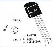
Using Transistor Circuit
The transistor used here may be taken as BC547. The logic signals are given by the micro-controller (ATMega 16/8 in our case).
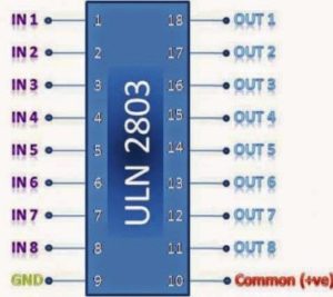
Using ULN2803 IC
- It is an inductor driver 18 pin DIP.
- Darlington Pair transistor is used (in open collector mode)
- 7-channel IC
- Works in sinking mode only, because logic ‘1’ at the output is never possible on this IC.
DTMF Switch
The term DTMF stands forDual Tone Multiple Frequency.It is a system which consists of two frequencies superimposed over each other. Individual frequencies are chosen such that it is easy to design filters and easy to transmit the tones through a telephone line having the bandwidth of approximately 3.5 kHz. DTMF was not intended to be used for data transfer. It was meant to be used for sending the control signals along the telephone line. With standard decoders, it is possible to send 10 beeps per second i.e. 5 bits per second. DTMF standard specifies 50ms tones and 600ms duration between 2 successive tones.
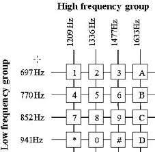
Nowadays DTMF is used for dialing the numbers in telephones, configuring telephone exchanges, etc. A CB transceiver of 2.7 MHz is normally used to send floating codes. DTMF was designed to be able to send codes using a microphone. Each beep is composed of two concurrent frequencies, which are superimposed on amplitude, the higher of the two frequencies is normally aloud by 1 dB, and this shift is termed as the twist. If the twist is equal to 4db, the higher frequency is loud by 4 dB. If the lower frequency is loud, then the twist is said to be negative.
Generating DTMF
How to generate DTMF signal. Well, the DTMF signal can be generated through dedicated ICs or by using RC networks connected to a microprocessor. MT880 is an example of a dedicated IC. But getting the latter method work is a bit difficult if high accuracy is needed. The crystal frequency needs to be sacrificed for a non-standard cycle length. Hence this method is used for simple applications, Most often, DTMF encoder software in P.C. or inbuilt dialing pulse of landline/ mobile can be used for the encoding purpose of generating DTMF signal.
Decoding DTMF
Detecting DTMF with satisfactory precision is a hard thing. Often, a dedicated IC such as MT8870 is used for this purpose. It uses two 6th order band-pass filters using switched-capacitor filters and it suppresses any harmonics. hence they can produce pretty good sine waves from the distorted input. Hence it is preferred.
Again microprocessor can also be used, but their application is limited.
DTMF Advantages
- By using this we can get a quick response.
- Not expensive to construct.
- High reliability and fast efficient.
- The consumption of power will be reduced and power efficiency will be increased.
- One can control the home appliances wirelessly by using this.
DTMF Applications
The applications of DTMF applications (Dual Tone Multi-Frequency Application) mainly involve the following.
- The DTMF is used to identify the dialed numbers in the telephone switching centers
- These are used to operate the remote transmitters in the terrestrial stations
- DTMF is applicable in IVR systems, home automation, call centers, security systems, as well as industrial applications.
That’s all regarding this Relay and DTMF. In next we will deal with the ADC, DAC their registers. So keep visiting to know more about the robotics sections.
Awesome!!