Introduction To Basic Components
In previous chapters, we discuss about AVR Studio, under that chapter we learned how to work in AVR Studio 5, how to create the project in the software and run the code, also we learned about how to give syntax in binary and hex in C language. Also in chapter 4, we discuss the embedded system, it’s basic part like number system, bit register etc.
Many of the students face the problem to understand the difference between microprocessor and microcontroller, so to clear that problem we provided the whole chapter on it name asMicrocontroller and Microprocessor.Now here we are discussing the basic component which is used inside the robotics or embedded system. Also for electronics engineer, this is the important chapter as it covers all the basic to the advanced component. Those who don’t know about the history orIntroduction of Roboticsthey can learn it by clicking on the link. In this chapter, we are covering all those optoelectronic devices which we will use in our project some are very common to all and some are new. So now let start to play with the component.
Light Emitting Diode (LED)
The Light Emitting Diode is an optoelectronic, passive type of semiconductor. It is used in many applications as a normal, color, infrared, ultraviolet light source, It’s small size, cheap cost, low power consumption etc. are some of its advantages over other light sources.
LED is a type of diode which emits light when it’s forward bias and not emit or OFF when it is reverse bias.
Note:Here the term forward bias means when the positive terminal of a diode connected with the positive terminal of a battery and the negative terminal of the diode is connected with the negative terminal of a battery.While
In the reverse bias, the positive terminal of a diode is connected with the negative terminal of a battery and the negative terminal of the diode is connected with the positive terminal of a battery.
LED is a small, low power consumption capability, faster switching, efficient compared with the other sources.
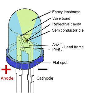
Fig 6.1: LED
Interfacing Of LED With Microcontroller ATMega 16
Now to do the simulation or to make some basic and simple project with LED you must know how to do interfacing with LED through microcontroller ATMega 16.
If we connect with the previous chapter we studied about the Registers like DDRX, PORTX etc. Now this registers will be used while we doing the coding of microcontroller ATMega 16.
In order to interface LED with a microcontroller, we must follow the following steps:
- Making the DDR register of that pin/ port as output.
- Assign ‘1’, if you wish to glow the LED and ‘0’ if we want to not to glow LED i.e. “OFF”.
For Ex:
To glow a single LED at the 0th position in PORTB, the following code is used to write.
DDRB=0b00000001 // making 0th pin of PORTB as output
PORTB=0b00000001 // LED Connected to 0th pin of PORTB will ON
PORTB=0b00000000 // LED Connected to 0th pin of PORTB will OFF
Seven Segment Display
A seven segment display (SSD) is a representation of 8 LED. It is a form of electronic device for displaying the decimal number that is an alternative to the more complex dot-matrix displays. It is widely used in digital clocks, electronic meters, and other electronic devices for displaying numerical information.
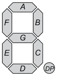
Fig 6.2: Seven Segment Display
Types Of SSD
There are 2 types of SSD i.e. Common anode and a common cathode.
Common Anode:In this type of SSD, the anode (positive) part of all 8 LEDs is made common. Thus, to select the LED we put‘0’ to that led.
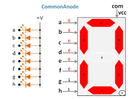
Fig: 6.3 Common Anode
Similarly, forCommon Cathodeall the cathode (negative) end of all 8 LEDs are made common and to select it we provide ‘1’ to that LED.
In Proteus, we connect the LED to the defined port i.e. Port A, B, C, D of the microcontroller from which we connect to it.
Binary Codes For Seven Segment Display
| Decoder Output | 7-segment Display Output | ||||||
|---|---|---|---|---|---|---|---|
| A | B | C | D | E | F | G | |
| 1 | 1 | 1 | 1 | 1 | 1 | 0 | 0 |
| 0 | 1 | 1 | 0 | 0 | 0 | 0 | 1 |
| 0 | 1 | 1 | 0 | 0 | 0 | 0 | 2 |
| 1 | 1 | 1 | 1 | 0 | 0 | 1 | 3 |
| 0 | 1 | 1 | 0 | 0 | 1 | 1 | 4 |
| 1 | 0 | 1 | 1 | 0 | 1 | 1 | 5 |
| 0 | 0 | 1 | 1 | 1 | 1 | 1 | 6 |
| 1 | 1 | 1 | 0 | 0 | 0 | 0 | 7 |
| 1 | 1 | 1 | 1 | 1 | 1 | 1 | 8 |
| 1 | 1 | 1 | 0 | 0 | 1 | 1 | 9 |
Interfacing SSD With Microcontroller
Let assume that SSD is connected with PORTC and PORTD (5 pins on PORTC and 5 pins on PORTD). Inside an SSD, we have 8 pins for the 8 LEDs, two pins for VCC supply (3 and 8 pins). Before starting the program we need to find out the type of SSD i.e. whether it is the common anode or common cathode.
For a practical base, we use the multimeter to identify the common anode and common cathode. For Common Cathode, pin 3 and 8 must be connected to ground or logic ‘0’ and other pins should be connected to logic ‘1’. From the above truth table, we supply the logic ‘1’ (VCC) and logic ‘0’ to the respective pin of SSD.
Note: We can display only a single digit number on a single seven-segment display at a time.
Now how to use this seven segment display in programming purpose. We providing here the code from which you capable to do the program and do simulations on the Proteus.
// Program for displaying single digit on SSD
#include
#include
int main () // all the program we will is of the integer type and main () is the old style declaration which will take an unspecified number of arguments.
{
DDRD=0xFF; // making Port D as a output.
DDRC=0xFF; // making Port C as Output.
while (1)
{
PORTD=0b00001011; // for displaying 0 also here we use the port D because we have taken this as an output pin by using the DDRD. In the above code we declared as DDRD=0xFF making it as a high.
PORTC=0b00011010;
} // while loop closed
return (0);
} // main loopp closed.
This is the very simple and basic program for displaying 0 and 1 in a common SSD.
We will discuss more code regarding the SSD later on.
There are some drawbacks of SSD i.e. most of the seven segments displaying the 16 hexadecimal characters. Some can display the number through 0 to 9 only so to overcome this type of problem an LCD (liquid crystal display).
Liquid Crystal Display (LCD)
The term LCD stands for the “Liquid Crystal Displays”. LCD is so much in vogue these days; in fact, most of the people cannot get through their day without using one. This technology is utilized in television, digital clocks, microwave ovens, calculators, thermometers and even in stereos. There is no limit bar for the application of LCD. So it would not be any surprise that this technology has revolutionized.
As in the full form of LCD, a Liquid word is come but do you know what this liquid is. It’s basically a new state matter ‘Forth State’, under which crystal is melt up to a stage where it is at converting stage in liquid. This state of matter is quite useful for displaying values. There are numerious types of liquid used for this purpose as pneumatic liquid and so on.
Note:Pneumatic liquid works on the concept of polarization which consists of twisted and untwisted pairs, means there will be twisted and untwisted pair crystals of this pneumatic liquid, whenever any datum is to be printed onto display that time these twisted pair turns to untwisted pair and then light will block which continuously passing through blacklight LED. As this crystal becomes untwisted that particular crystal block the light and that datum is printed on display.
There are 2 types of LCDs used nowadays for displaying data:
- Alphanumeric LCD
- Graphical LCD
Alphanumeric LCD
An alphanumeric LCD is a liquid crystal display and its purpose is to display the number and letters. In basic LCD liquid crystal is placed between transparent electrodes, and which changes the polarization of the passing light in the electrical field. The electrodes are covered by a polarization filter, which assures that only one polarized light can pass through the screen. If the liquid crystal changes its polarity due to an electric field, the light can’t pass the screen or part of it and it looks dark.
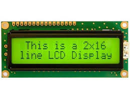
Fig 6.4: Alphanumeric LCD
Graphical LCD
The graphical LCD is used to display customized character and images. This LCD has many application they are used in video games, mobile phones, lifts etc. as the display unit. Various type of graphical LCD is available in the market.
Winster display is a professional character and graphical LCD manufacturer. The LCD of this manufacturer is available in dot matrix format of graphical resolution including 122*32, 128*64, 128*128, 144*32, 160*128, 160*160, 160*32, 160*80, 192*64, 192*128, 240*64, 320*240 and etc.
The size are including 3″ LCD, 3.2″ LCD, 4″ LCD display and etc.
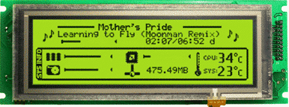
Fig 6.5 Graphical LCD
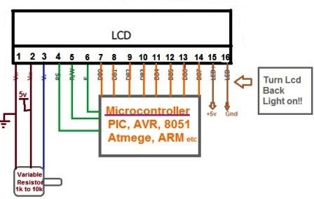
Pin Description Of LCD
Pin no. | Function | Name |
|---|---|---|
| 1 | Ground (0 V) | Vss |
| 2 | Supply voltage; 5V | Vcc |
| 3 | Contrast adjustment | Vo |
| 4 | High to display data; Low for instruction code | Register select (RS) |
| 5 | Low to write to the register; High to read from the register | Read/Write (R/W) |
| 6 | Reads data when high; Writes data at high to low transition (falling edge) | Enable (EN) |
| 7 | 8-bit data pins | DB0 |
| 8 | DB1 | |
| 9 | DB2 | |
| 10 | DB3 | |
| 11 | DB4 | |
| 12 | DB5 | |
| 13 | DB6 | |
| 14 | DB7 | |
| 15 | Chip selection for IC1; Active high | CS1 |
| 16 | Chip selection for IC2; Active high | CS2 |
| 17 | Reset signal; Active low | RST |
| 18 | The output voltage for LCD driving | Vout |
| 19 | Backlight VCC (5V) | LED A |
| 20 | Backlight Ground (0V) | LED K |
Before we start interfacing part we should firstly know how characters can display on display screen and which type of characters and display. Actually, there is a limitation on the characters that can be displayed.
Note:In LCD we can’t display Urdu, Arabic, Punjabi characters and so on. English characters and numbers, arrow keys and some more character only can be displayed. But if we want to display any special character like the bell, any special figure, these can also be displayed but first, we would creating these special characters and then would be using same like we’ll use the other characters.
How To Do Interfacing With Alphanumeric LCD
Now let’s play with the display. As we can see from the LCD pin diagram there are 8 data pins means data can be transferred from these pins. There is 2 Hitachi microcontroller named as HT44780 inside the 16*2 LCD. They control the entire event occurring inside the LCD and its complete working. The data from the microcontroller to microcontroller inside the LCD can be transferred in 2 ways; either data can travel using all data pins or using 4 data pins only i.e. we have 2 modes of operation.
- 8-bit mode
- 4-bit mode
8-Bit Mode:
To understanding both the concept let’s take an example, as we can see there is a block diagram. In Proteus, we take LCD and ATMega16. We define one port as an output port. Now suppose we take Port D as an output port. Then the pin configuration of LCD will take place as shown in the figure.
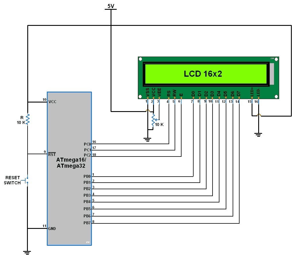
Note: There are 4 ports available in microcontroller as I/ O ports; any one of these can be used for connecting LCD with the microcontroller. We have a maximum of 8-bit port available with us microcontroller. So we’ll be using two ports of our microcontroller, as we have three control pins (RS, R/ W, and EN) while 8 data pins, so a total of 11 pins (if all the power pins are permanently connected in the system).
It should be noted that all control bits and data bits, should be synchronized otherwise there might be any problem in displaying character.
Some Important Point
- A 16*4 LCD can be used in three modes: 16*1, 16*2 and 16*4. Similarly, other LCD can also be used in different modes. So before displaying any character we need to tell the Hitachi’s microcontroller about the mode in which we want the microcontroller to operate the LCD.
- whether we want the backlight ‘ON’ and ‘OFF’.
- The most important is the mode of data transfer: 8-bit mode or 4-bit mode.
- the starting location for displaying the first character.
In this chapter, we deal with some of the optoelectronic devices like LCD, SSD etc. This all regarding this chapter next we will deal with the function of the LCD and the other topics. If you have some problem please tell us through the comment box given below. Our team will give the answer to your queries.