
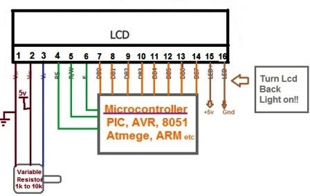
Previously at we observed we learn about some basic components like LED, LCD, etc. In LCD we learn about how to initialize it if it is in 8-bit mode. Now in this chapter, we will learn about to initialize LCD in 4-bit mode, how to send data on LCD (hardware) through the software. Now if you remember chapter 5 AVR Studio we learn about to burn the program using the USBASP. Now in this post, we will learn about the various program of LCD which will help you in the future also.
Functions For LCD {Programming}
Before starting this let’s see what we have done so far. In our first post, we learn about the robotics introduction its mechanism and laws. As we know that to make any of electronics project we need a microcontroller and microprocessor as nowadays controller takes place over the processor so we will also make our whole project over the microcontroller which is ATMega 16. So let’s start with the LCD and its coding.
Function For LCD Initialization
void LCD_intialize_4bit()
{
LCD_inst_4bit(0x02); //return to home
LCD_inst_4bit(0x28); //use 4-bit mode
LCD_inst_4bit(0x0c); // display ON, Cursor OFF
LCD_inst_4bit(0x06); //Entry mode
}
Function For Sending Data On LCD
void LCD_data_4bit(unsingned int data)
{
unsigned int UN,LN;
UN=x & 0xF0; //only higher nibble is processed
lcd=0b000000101|UN; //data mode
_delay_ms(2);
lcd=0b00000001|UN; //reset EN only
_delay_ms(2);
LN=(x<<4) & 0xF0; //next nibble is processed
lcd=0b00000101|LN; //data mode
_delay_ms(2);
LCD=0b00000001|LN; //Reset EN only
_delay_ms(2);
}
These are the functions which are used for displaying an alphanumeric characters using 4 bit mode. But if someone is interested to display his/ her name then it can also be done. Following function will be used in order to diusplay the name in the LCD.
//Function for a string
void LCD_sentence_4bit(char*str)
{
int i=0;
while(str[i]!=’\0′)
{
LCD_data_4bit(str[i]); //4 bit mode function for data
i++;
}
}
Explanation Of Above Code
In the first line we have created function and passed a string type of argument to it. We have takken an integer type variable and intialized it with zero for using it till end of the string doesn’t meet. Every string ends with‘NULL’ character. So we’ll check condition in while loop. Until the ‘NULL’ is found, keep on dispalying the character on the LCD. Whenver this null character is found this loop terminates.
//Function For Displaying Any Number
void LCD_multidigit_4bit(unsigned int num)
{
LCD_cmd (0x04);
unsigned int d=0;
while(num!=0)
{
d=abc%10;
LCD_data(d+48); //display digit
num=num/10;
}
LCD_cmd(0x06); // auto increment mode
}
Expnatnation of Above Code
First we created the function with an integer type of argument. Let’s understand this function with an example.
If number=1534; then it will be copied to num (variable, see in function) and now will work with this new variable. The loop first checks whether the number enter in zero or not. The answer is ‘NO’, so the loop continues to the next instruction inside the loop. We have taken a new variable d and for d=num%10 -> (1534%10=4) means d=4, now let’s display it on the LCD.
We did d+48 in the code because ’48’ is the ASCII code for ‘ 0’. Now, d means 4+48=52 and this 52 is an ASCII value for number 4. It will display on specified location given by us. After that num=num/10; means 1534/10=153, this is the new value of the variable ‘num’. This loop will again check whether this variable is equal to zero or not. If the result is ‘No’, then the process is repeated again. it has been already started that we can display only limited characters on the LCD whose patterns are available in the memory of the LCD. To understand the complete concept and learn how we can display our own created pattern on the LCD, let’s have a look at the memory mapping of LCD.
Memory Mapping in 16*2 LCD
The memory of an LCD is divided into 3 regions. They are:
- CGROM (Character generation read only memory)
- DDRAM (Display data random access memory)
- CGRAM (Character generation random access memory)
Let’s have a look at these memories one by one
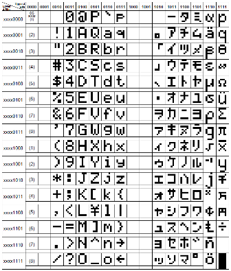
CGROM (Character Generation ROM)
This is the memory area where all the predefined patterns are stored. The patterns are drawn in this memory area at the time of LCD manufacturing. The patterns are stored such that their memory address is equivalent to the ASCII code for that pattern e.g. A pattern in the form their memory address is equivalent to the ASCII code for that pattern e.g. A pattern in the form of ‘A’ is located at the 65th memory location in CGROM memory area. So when you pass 65 to the Hitachi’s microcontroller to print ‘A’ on the LCD, actually the controller doesn’t know what is ‘A’ or ‘B’ or any other character. It just takes the binary value of 65 from DR, passes this value to CGROM, CGROM they check what’s there on the 65th memory location and prints the patterns on the given DDRAM address. Now, let’s have a look at the characters stored in this memory.
DDRAM (Display Data RAM)
DDRAM is the memory area used for displaying character. This is a memory area associated with the display area on the LCD. A maximum of 80 characters can be stored in this memory out of which only 32 characters are visible at a time on the LCD screen.
These 32 characters are displayed as 16 characters in one row and rest 16 in another row. It means that in each line LCD there are 40 character spaces available out of which only starting 16 characters are visible on the LCD screen. To display any character on the LCD, we pass the display location (DDRAM address) to the Hitachi’s microcontroller and then the character to be displayed. DDRAM memory address starts from 0x80 to 0xA7 in the first row and from 0xc0 to 0xE7 in the second row. Out of these character displayed on memory areas from 0x80 to 0x8f are visible on the first row and from 0xc0 to 0xCf are visible on the second row.
CGRAM (Character Generator RAM)
This area of the LCD memory is used when the user wants to create its own characters like a Bell-shaped, a heart shape or something else. These locations are used for accessing the user-defined characters created in CGRAM memory area.
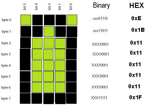
Creating User-Defined Characters
Each pattern/ character is designed in 5*7 dots matrix that means you have to design your desired characters in a matrix of 5 columns and 8 rows. Each CGRAM memory location is associated with one row of the matrix. SO to store a pattern/ character we consume 8 locations of CGRAM.
Thus we have total of 64 memory location of CGRAM, with the help of which we can create a maximum of 8 user defined characters. The first location of CGRAM has a memory address of 0x40 followed by 63 continuous CGRAM memory locations. Thus the first row of the user-defined character is written at 0x40, the second row at 0x41, then at 0x42 till 0x47. The second characters start from 0x48, the third character at 0x50 and so on. The last character starts at 0x77 and ends at 0x7f.
// Function for Creating Customized Character
void custom_char(){
LCD_inst_4bit(0x40); // satrting location of CGRAM, where you want to create the character
LCD_data_4bit(0x0a); // for the very first row in 5*8 dots
LCD_data_4bit(0x15);
LCD_data_4bit(0x11);
LCD_data_4bit(0x0a);
LCD_data_4bit(0x04);
LCD_data_4bit(0x00);
LCD_data_4bit(0x00); // code for last row in 5*8 dots
}
//Main Function to check all the functions created above
void main (){
DDRD=0xff; //set port D as output
LCD_intialize_4bit();
LCD_inst_4bit(0x01); //to clear LCD screen
_delay_ms(2);
LCD_inst_4bit(0x80); //move cursor to the begining of the first line
LCD_data_4bit(‘A’); //print character ‘A’ on LCD
LCD_inst_4bit(0x84); // move ciursor to the fifth position of second line
LCD_multidigit_4bit(786); //print a number 786 on LCD
custom_char(); // initalize custom_char function
LCD_inst_4bit(0xC5); //move cursor to 6th position of second line
LCD_data_4bit(0);
}
In this post we provided the complete informatiuion regarding the LCD programming and other topics like DDRAM, CGROM and CGROM. If their is any queries please tell us through the comment box given below. We will reply the answer of your queries.


Hii,
Although the LCD has been replaced by the LED but I need to know more about the LCD as it is covered in my semset syllabus. The details provided here is quite good but need to know more about in very deep. Can you please provide the details of it in brief in abother article, As on moving the concept of LED I first need to understand the proper concept on LCD. Pls share more details on it for the same article.