Previously in we observed we talked about some basic components of electronics which is used in the embedded system like LED, Seven Segment Display and LCD. In LCD we talked about the introduction, types of LCDs, Pin configuration of LCD, it’s interfacing and now in this post, we will talk about the how to initialize LCD (through coding) in AVR.
Before starting the new topics let’s talk about the previous chapter which we studied till now. Starting from chapter 1 we talked about the Introduction of Robotics in which we studied simple mechanism, types and history of robots by moving forward we studied about basics of microcontroller and microcontroller which is now used in every electronics items. Further, we step forward we talk about the Brain behind embedded system in chapter 3 in which we studied about the history of AVR. In chapter 4 we studied about the Number system and AVR along with few electronics components.
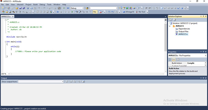
Now out of this, the most important topics from where all the sections of AVR begin are AVR Studio, Intro and installation process. In this chapter, we studied about how to install AVR and do work in the software. Now after such a long process, we begin our topics which left in the previous chapter i.e. 6. In this chapter, we are dealing with the initialization of LCD, sending a command in an LCD and mode of LCD. So check out this complete topic from here.
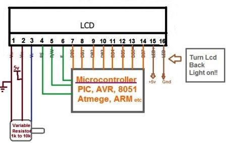
Fig: LCD Interfacing With ATmega 16
Before starting coding you must know that in every LCD there is backlight available also the starting location of LCD as from home position means from 0x80 location, for displaying the first character.
For intializing LCD following code will be use
Void LCD_intialize_8bit()
{
LCD_inst_8bit (0x02); // home position
LCD_inst_8bit (0x38); // Set: 8-bit, 16*2 and 5*7 dots
LCD_inst_8bit (0x06); // Entry Mode
LCD_inst_8bit (0x0c);
}
Don’t get confused with the codes 0x02, 0x38, 0x06, 0x0c used in these lines, as these are the commands inside the Hitachi’s microcontroller for telling the microcontroller that we want to put the LCD in the modes we desire. These are provided to us by the LCD manufacturer.
Notice, look at the functions (LCD_cmd) used inside the above function LCD_init for initialization, it consists of two parts:
- The name of the function
- The value/ argument in the brackets. The codes inside the brackets have already been explained in the above paragraph.
The function used to pass the values has a definition given below.
Sending a Command
Now take a look at how to transfer a command/ data from the AVR Controller to the Hitachi Microcontroller. The ‘RS’ pin stands for Register Selectpin that simply means that it used for selecting among the registers of the LCD.
The LCD has got two buffers which are named as
- Instruction Buffer
- Data Register
Commonly the problem which arises is the binary numbers available to the Hitachi microcontroller on the data pins of the LCD are commands or data? This problem is solved by selecting the register where these binary codes will be stored. If the user selects IR (instruction Register, RS=0), then the microcontroller understands it and treat the binary numbers as commands and vice versa.
If the user selects IR (Instruction register, RS=0), then the microcontroller understands it and treat the binary numbers as commands and vice versa if the user selects the DR (data register). So the first task of the user is to select the register so that the microcontroller understands the data being fetched.
The second control signal is the RW pin. It is theRead/ Write pin. If RW=0, that means that the user wants to write on the LCD and if we want to read from the LCD then we will put RW=1, that means that the user wants to read the LCD.
The third control signal is the EN pin. It stands for ‘Enable’. It acts as a lock at the entrance of the LCD. When enabled (EN=1), it allows the binary number owns the data pins of the LCD to enter the buffers. So when the user wants the data to enter the buffer, he/ she enter provides a logic ‘1’ on this pin otherwise it remains close (so that no garbage value can enter the LCD system).
Let’s summarizes all the steps required in order to send a command/ data from the AVR microcontroller on the development board to the Hitachi’s microcontroller inside the LCD.
- Select the register by the help of RS pin.
- Select the reading/ writing mode bt the help RW pin.
- Enable the EN for data to get into the buffers (IR/ DR).
- Place the data on the data pins.
- Disable the EN pin to prevent garbage value to the enter the LCD system.
For Command Mode
RS=0;
R/W=0;
EN=1;
_delay_ms(2);
EN=0;
For Data Mode
RS=1;
R/W=0
EN=1;
_delay_ms(2);
EN=0;
Let’s have a look to the function one more time and try to understand the complete procedure in terms of codes.
//Function for sending command
#define lcd PORTD
void LCD_inst_8bit(unsigned int x)
{
lcd=x;
PORTC=0b00000100; //RS, R/ W, EN at PB0-PB2; comamnd mode
_delay_ms(1);
PORTC=0b00000000; //to reset EN pin only
}
// Function for writing data
{
lcd=data;
PORTC=0b00000101; //data mode
_delay_ms(2);
PORTC=0b00000001; //Reset EN only
}
4 Bit Mode
In 8 bit mode, we used the complete port of the AVR microcontroller for transferring the 8-bit data from the AVR microcontroller to the Hitachi’s microcontroller, but if we have lesser number pins available then we will use the 4-bit mode of operation of LCD to our remedies.
The benefit of 4-bit mode over the 8-bit mode of LCD is, previously we were using four ports of our microcontroller and now we were using two ports of our microcontroller. So we saved our two ports of LCD.
Note:As we already know about the MSB (Most Significant Bit) contribute more in data that’s why we always prefer doing work with the MSB bits first. There’ll send higher 4 bits of our 8 bits data first and then the rest bits.
It is easy to send the upper nibble because they are directly connected to the data pins of the LCD. To transfer the lower nibble, we will left shift 8-bit data by 4 towards left, make the lower bits as higher bits and will transfer them in a similar fashion as the higher nibble.
So before sending the data bits, we need to apply all the theory above to them. This is done by creating two more functions when working in 4 bit. Not only that we need to tell the microcontroller (µc) that, we will be using it in 4-bit mode. So complete function list for working in 4-bit mode is summarized below.
// Function for sending a command
#define lcd PORTD
void LCD_inst_4bit(unsigned int inst)
{
unsigned int UN, LN;
UN= inst&0xf0; //Higher nibble is processed only
lcd=0b00000100|lcd; //commanding mode
_delay_ms(2);
lcd=0b00000000|lcd; //to reset EN pin only
_delay_ms(2);
LN=(inst<<4)& 0xF0; //next nibble is processed
lcd=0b00000100|LN; //commanding mode
_delay_ms(1);
LCD=0b0000000|lcd; //to reset EN pin only
_delay_ms(2);
}
That’s all in this chapter, In the next chapter, we will deal with the functions of LCD. If you are interested in making projects then stay connect with us. We will provide you more details about this.